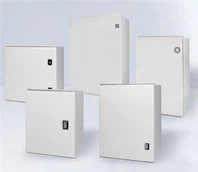
Electric meter enclosure specification:
Normative references
The clauses in the following documents have become clauses of this specification after being quoted in this specification. For dated reference documents, all subsequent amendments (excluding errata content) or revisions do not apply to this specification. For undated reference documents, the latest version is applicable to this specification.
GB 4208-93 Enclosure protection grade (IP code)
GB 7251.1-97 low-voltage switchgear and control equipment
DL/T 448-2000 Technical Management Regulations for Electric Energy Metering Devices
JB/T 16934-1997 electric energy metering cabinet
DL/T 5137-2001 Electric measurement and electric energy metering device design technical regulations
GB/T 17626.4-1998 Electromagnetic compatibility test and measurement technology Electrical fast transient pulse group immunity test
External assessment:
1electric meter enclosure box identification
1.1 The metering box should have the equipment nameplate, factory number, and factory date. The uniform numbering rule number of the metering box shall be provided by the ordering party.
1.2 The State Grid Corporation corporate logo is located on the upper part of the entry room door; the safety warning logo is located in the middle of the entry room door; the nameplate is located under the entry room door; the power supply service hotline 95598 logo is located in the middle of the exit room door.
3 Electric meter cabinet material: Polycarbon non-metallic material PC
| Box material reference table | Environmental conditions | Material type | Material thickness (mm) | Enclosure rating |
| Integral combination non-metallic metering box | -15℃~45℃ | PC | 3.0~4.0 | IP33 |
4 electrical components
The metering box should be equipped with hierarchical protection to meet the requirements of selectivity and sensitivity. Molded case circuit breakers should meet the requirements of GB/T 14048.2; single-phase circuit breakers should meet the requirements of GB 10963.1. The electrical components in the box should pass compulsory certification (3C certification) in accordance with relevant national regulations

5 Installation accessories
5.1 The meter box should have rainproof measures.
5.2 The insulated copper wire for wiring of each meter shall not be less than 10mm2.
5.3 The neutral line of each electric energy meter in the multi-meter metering box should be installed separately and not shared.
5.4 Insulated and flame-retardant wires should be used in the metering box, and the color code should be: the phase wire is yellow, green and red; the neutral wire is black; the PE wire is a yellow-green two-color wire.
5.5 Wire slot wiring is also used in the metering box, the incoming and outgoing wires are separated independently, the wiring design is reasonable, and the craftsmanship is passed.
5.6 Each table position must have a number, and the "Property Demarcation Point" mark should be set on the entry line at the outlet end of the meter.
5.7 PE terminals must be reserved in the non-metal box to facilitate reliable connection between the box body and the grounding grid.
6 Electric meter box cabinet
The electric meter box body must be a closed structure, and have a good ventilation and heat dissipation structure design. The heat dissipation holes should have rainproof function and be equipped with protective nets. Measures should be taken to prevent external foreign objects from being inserted and touching the live conductor under abnormal conditions.

7 Function rooms
The metering box needs to be divided into three parts: the incoming line room, the metering room and the outgoing line room. The necessary interlocking logical relationship between the incoming line room, the metering room, and the outgoing switch room needs to be interlocked to meet the needs of different professional rooms of the power supply company. And the division of responsibilities between power supply companies and power customers. The rooms can be arranged in horizontal, vertical and mixed types.
8 Partitions and doors
8.1 The doors of the entry room, the metering room and the exit room of the multi-epitome meter box are all independent. It should be built-in design, and the door shaft should have anti-pry measures; there should be no exposed and accessible fasteners outside the door.
8.2 The colorless and transparent explosion-proof material of the metering room door meets the requirements of meter reading management and anti-electricity theft. The frame should have good sealing performance. The installation location of the collector should be convenient for infrared debugging terminal and unit data collection.
8.3 The outlet room adopts a two-layer door structure. The second-layer door should be able to prevent unconscious direct contact with live conductors, but cannot prevent conscious behavior.
8.4 The incoming line room should be equipped with incoming line switches, branch busbars, terminal collectors, neutral terminals, etc. (The capacity of the sub-line busbar should meet the requirements of the number of meter households)
8.5 The first floor door of the outlet room can be opened conveniently, and the second floor door is controlled by a key or a metering indoor pin, and the operating handle of the line switch is exposed outside.
9 Lock and seal
9.1 The entrance room and metering room door of the electric energy metering box must be equipped with special door locks, and certain protective measures must be taken outside the door locks. The incoming switch room and the metering room are controlled by a lock, which cannot be opened normally without authorization during normal operation. The non-metal watch box lock ear should be able to be replaced if it is damaged.
9.2 The lock should have certain anti-theft and anti-pry performance, and should pass the corresponding safety certification. In addition, the metering room needs to be sealed with lead, and the lock and seal should have protective measures. In order to standardize the management of metering seals and locks.
9.3 It can be equipped with the function of users to operate the patrol display button of the electric energy meter according to the needs.
10 Equipment layout
10.1 Directly connected metering box should be equipped with incoming line switch room, metering room and outgoing switch room; through transformer-connected metering box should be equipped with incoming line switch room, metering room, transformer room and outgoing switch room. Each functional area should be separated independently, and the collector should be installed in the incoming switch room.
10.2 The electric energy meter and the electricity consumption information collection terminal shall be respectively installed on the fixed fixture, mounting frame or grid plate.
10.3 The horizontal distance between the electric energy meter and the electric energy meter should not be less than 30mm, and the vertical distance should not be less than 80mm;
10.4 The distance between the test junction box, electric energy meter, electricity information collection terminal and the shell shall not be less than 60mm;
10.5 The distance between the front of the electric energy meter and the observation window should be between 20mm;
10.6 The vertical distance between the electric energy meter, the electricity consumption information collection terminal and the test junction box shall not be less than 40mm;
10.7 The horizontal distance between the electric energy meter and the electricity consumption information collection terminal shall not be less than 80mm.
11 Function configuration
11.1 The metering box can realize functions such as remote fee control and power outage, and the equipment configuration should be able to meet the requirements of electricity information collection terminals, smart meter types and technical specifications. The up and down channels of signal lines and cables for communication and control should be reserved to ensure the smooth flow of communication and control.
11.2 The direct access type electric energy meter should choose the built-in trip relay to realize management control
12 permutations
The arrangement of the multi-meter metering box to measure the indoor electric energy meter from left to right is the 1st way, the 2nd way...the Nth way. The height of the multi-epitome metering box and the relative position of each component should be kept as uniform as possible to facilitate later assembly.
13 wiring requirements in the box
13.1 The quality of the wire installation process in the box should meet the relevant standards, the wiring is correct, the electrical connection is reliable, the contact is good, the wiring is neat and beautiful, and the wire is not damaged.
13.2 The current and voltage loop wires should be insulated copper wires, and there should be no joints in the middle, and there should be no contacts or terminals except the test junction box.
13.3 The voltage and current loop wires should be equipped with terminal numbers that conform to the drawings, and the wire arrangement sequence should be in the positive phase sequence (that is, the yellow, green, and red wires are from left to right or top to bottom).
13.4 The 485 communication line should be connected in parallel according to the horizontal arrangement of meters and connected to the collector through the terminal; the power cord of the collector and alarm should be connected through the terminal.